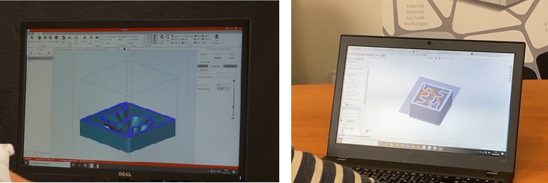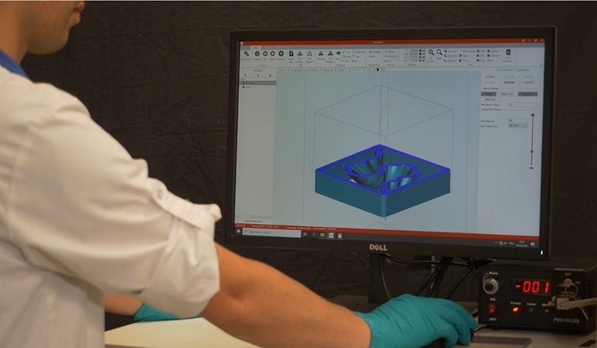
It is an integrated plug-in, developed by 3DCeram, to edit your STL file and make the CAD file preparation much easier.
Built-It is an integrated tool in option
Let’s review the time-saving functions…
Build-It is user-friendly plug-in for you to keep focused on the final part design and save time on the requirements of the printing process. It is an intuitive interface which allows any operator to set the design file for printing.
Build-It, is a tool box which makes you save time thanks to its several functions:
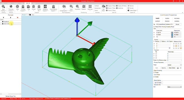
The translation & rotation function helps to place the part(s) on the build platform, to secure the printing which is so important.
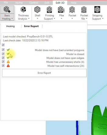
The next operation is to check the file and fix errors that can happen on a STL file. It takes only few clicks to generate the analysis and to heal the file.
For the beginners, there’s the default process which will fix automatically the errors. Then the file is clean!
The next step would be to take care of the thermal post processing of the part. That means to anticipate the shrinkage, depending on the paste or slurry used.
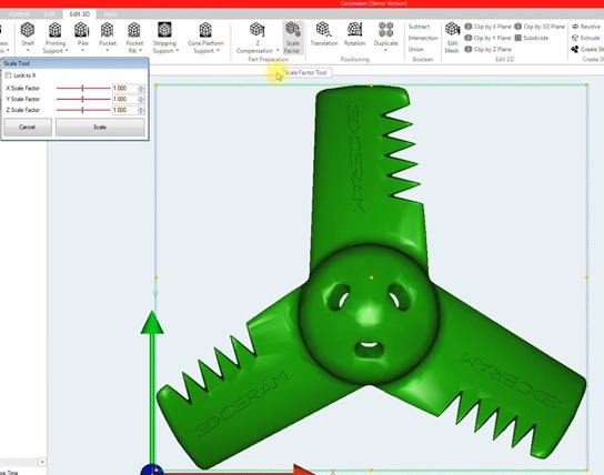
Build-it allows to scale the model in the 3 printing directions. So you can either have the same shrinkage coefficient for the 3 directions or a different one depending on the printing coordinate system. The shrinkage coefficients depends on the material we are using. Make sure to input the correct values, you can check on the paste or slurry container.
When the part is scaled, the Z compensation can be applied on the part to compensate the curing depth off the laser on the paste or slurry. It impacts directly on the dimensions of the parts and to get the best accuracy after the printing step. The Z compensation depends on the ceramic paste or slurry. The values are provided with the material.
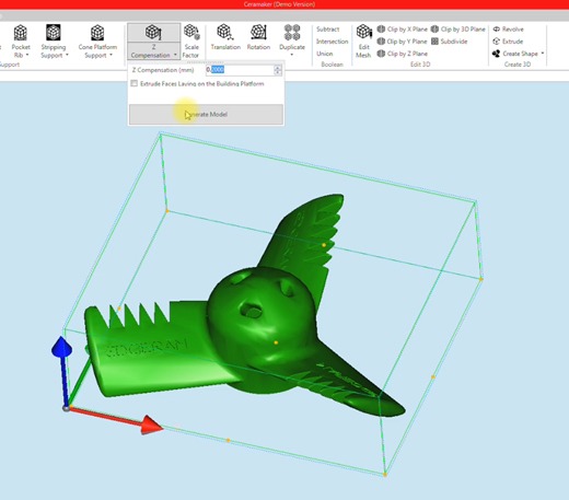
This step is one of the most time consuming operation in a CAD software. With Build-It it will take 2 clicks.
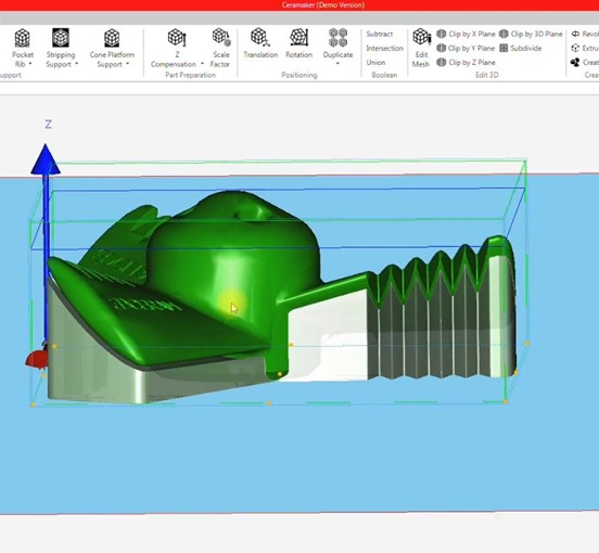
Another function to save time, is the printing support one ! it allows to create a free link technology support for the model. The free link technology is a smart support adapted to complex geometries exclusive to 3DCeram.
You can create either a bottom support which will help for the printing process or a top support needed for thermal post processing. Several parameters are available which will ease the process of design. Here are the two main parameters:
You can choose an offset from the part which will be the distance between the part and the support in Z direction. It will define the paste thickness between part and the support. Then it must be adjusted depending on the material.
The overhang surface, which is the angle between the surface which needs to be supported and the building platform.
The support is generated very easily and the gap distance between the part and the support is generated automatically without any design skills.
Among all the functions, pockets creation can be usefull. Sometimes the printing support can be quite massive, so in order to lighten it, we use the pocket function. This function allows to create a pocket into the printing support.
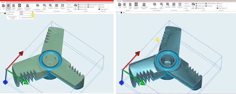
Of course, it is possible to generate the pocket either for the bottom or the top support, depending on what you have created before. The pocket can be generated in 2 clicks easily when in a CAD software it would take much more time to do so.
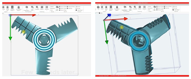
If the support is large, creating a pocket could lead to large surfaces which are not supported, and it can fail during printing. To avoid this situation, the Rib function reinforces the pocket by creating pocket ribs.
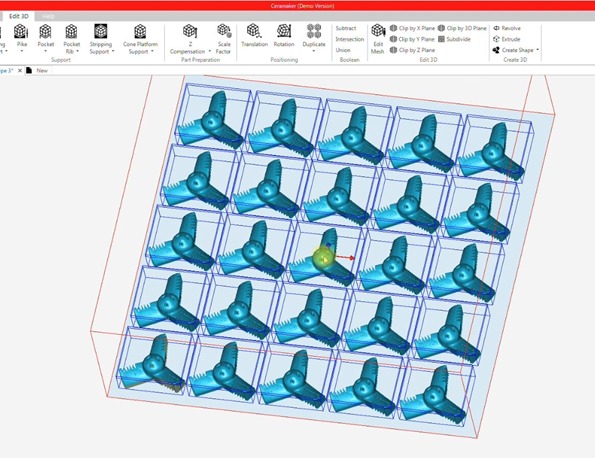
The function Duplicate requires a few information, like the number of parts wanted to be added along the axis and also the gap between the parts. The parts and the supports are then duplicated keeping the alignment between each item.
Work your file remotly from the office and then load the file on the printer to start the printing run.
